

The PCF8591 is a single-chip, single‑supply low‑power 8‑bit CMOS data acquisition device with four analog inputs, one analog output and a serial I²C‑bus interface. Three address pins A0, A1 and A2 are used for programming the hardware address, allowing the use of up to eight devices connected to the I²C‑bus without additional hardware. Address, control and data to and from the device are transferred serially via the two-line bidirectional I²C‑bus.
The functions of the device include analog input multiplexing, on-chip track and hold function, 8-bit analog‑to‑digital conversion and an 8‑bit digital‑to‑analog conversion. The maximum conversion rate is given by the maximum speed of the I²C-bus.
Features
- Single power supply
- Operating supply voltage 2.5 V to 6.0 V
- Low standby current
- Serial input/output via I²C-bus
- I²C address selection by 3 hardware address pins
- Max sampling rate given by I²C-bus speed
- 4 analog inputs configurable as single ended or differential inputs
- Auto-incremented channel selection
- Analog voltage range from VSS to VDD
- On-chip track and hold circuit
- 8-bit successive approximation A/D conversion
- Multiplying DAC with one analog output.
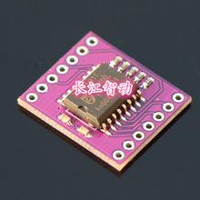
This is the module that I used in this example, there are a couple of variants that work as well
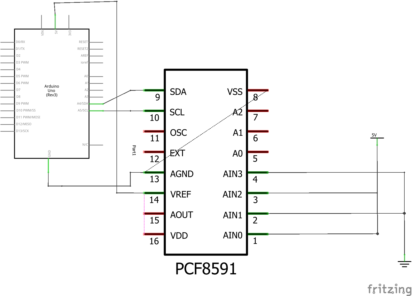
Schematic
I have not been able to find a schematic of the CJMCu-8591 module, the following is the connections that I made to make the code work. I simply connected the analog inputs to gnd and vcc, you could connect these to a pot for testing as well
Code
[codesyntax lang=”cpp”]
#include "Wire.h"

#define PCF8591 (0x90 >> 1)
byte adcvalue0, adcvalue1, adcvalue2, adcvalue3;

void setup()
{
 Wire.begin();
 Serial.begin(9600);
}

void loop()
{
 Wire.beginTransmission(PCF8591);
 Wire.write(0x04);
 Wire.endTransmission();
 Wire.requestFrom(PCF8591, 5);

 adcvalue0=Wire.read();
 adcvalue0=Wire.read();
 adcvalue1=Wire.read();
 adcvalue2=Wire.read();
 adcvalue3=Wire.read();

 Serial.print(adcvalue0);
 Serial.print(" ,");
 Serial.print(adcvalue1);
 Serial.print(" ,");
 Serial.print(adcvalue2);
 Serial.print(" ,");
 Serial.print(adcvalue3);
 Serial.println();

 delay(1000);
}
[/codesyntax]
Output
Open the serial monitor and should you see something like this which is what you would expect since the Analog inputs are connected to 5v and Gnd in this example
255 ,0 ,255 ,0
255 ,0 ,255 ,0
255 ,0 ,255 ,0
255 ,0 ,255 ,0
255 ,0 ,255 ,0
255 ,0 ,255 ,0
255 ,0 ,255 ,0
Links
PCF8591 AD/DA Converter Module Analog To Digital Conversion+Cable